1、安裝好Arduino IDE程式,並裝好Aduino Mega 2560的驅動程式
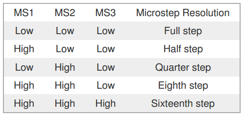
2、將RamPs1.4模組組裝到Mega 2560上,並將RamPs1.4上的步進馬達Jumpper選擇至所需的檔位
3、插入A4988步進馬達驅動器組裝至RamPs1.4上。請注意方向


此S1X/S2X為0.1歐姆【電流設定提生= R200=0.2歐姆 < R100=0.1歐姆】;鍍金排針(導電能力提高,相容性提生)
線路板覆銅厚度升級到2oz,銅皮厚度70um,普通的是35um,含銅量更高,
散熱性能更好。
電流調整公式說明:
itripmax【電流】 = vref【可調電壓】 / ( 8 x 【歐姆 】)
按本規格範例:電流=0.96v可調電壓/(8x0.1歐姆)=1.2A電流
調整說明(教學):【一定要調整足夠的電流(按自已測試為原則),因為這樣才不會步進馬失步,另外切記調整時請放平調整,不要掛在邊邊後調整,這樣很容易失手讓板子秀斗,因為常常秀斗後還是可以正常用,但是怕已傷了板子本身。也查不出原因為什麼會列印失敗。】
準備工具三用電表、調整縲絲起子、已將電源供應器接上主機板上並送電完成
4、將12V電源供應器電源打開,此時請測量並調整步進馬達應該有的電壓,電流偏差太大可能導致馬達不轉動、轉動不正常、不夠力、失步甚至燒毀馬達或控制A4988晶片。
5、A4988一般來說是不需要加散熱片,如果買來就有也不需要拆掉,如果原來沒散熱片而您確定有需要,請安裝適合的大小,太大會太近旁邊的PIN腳造成短路。
6、調整好之後關閉電源再插上步進馬達,重新再開啟電源並連接USB將程式Updata至主板(程式如下),觀察馬達是否正常運轉,馬達線順序是否正確,不正確造成電流相位不正常,運轉不順暢,然後再次確認A4988電流設定調整正確
測試程式:如下
#define X_STEP_PIN         54
#define X_DIR_PIN          55
#define X_ENABLE_PIN       38
#define X_MIN_PIN           3
#define X_MAX_PIN           2

#define Y_STEP_PIN         60
#define Y_DIR_PIN          61
#define Y_ENABLE_PIN       56
#define Y_MIN_PIN          14
#define Y_MAX_PIN          15

#define Z_STEP_PIN         46
#define Z_DIR_PIN          48
#define Z_ENABLE_PIN       62
#define Z_MIN_PIN          18
#define Z_MAX_PIN          19

#define E_STEP_PIN         26
#define E_DIR_PIN          28
#define E_ENABLE_PIN       24

#define Q_STEP_PIN         36
#define Q_DIR_PIN          34
#define Q_ENABLE_PIN       30

#define SDPOWER            -1
#define SDSS               53
#define LED_PIN            13

#define FAN_PIN            9

#define PS_ON_PIN          12
#define KILL_PIN           -1

#define HEATER_0_PIN       10
#define HEATER_1_PIN       8
#define TEMP_0_PIN          13   // ANALOG NUMBERING
#define TEMP_1_PIN          14   // ANALOG NUMBERING

void setup() {
  pinMode(FAN_PIN , OUTPUT);
  pinMode(HEATER_0_PIN , OUTPUT);
  pinMode(HEATER_1_PIN , OUTPUT);
  pinMode(LED_PIN  , OUTPUT);

  pinMode(X_STEP_PIN  , OUTPUT);
  pinMode(X_DIR_PIN    , OUTPUT);
  pinMode(X_ENABLE_PIN    , OUTPUT);

  pinMode(Y_STEP_PIN  , OUTPUT);
  pinMode(Y_DIR_PIN    , OUTPUT);
  pinMode(Y_ENABLE_PIN    , OUTPUT);

  pinMode(Z_STEP_PIN  , OUTPUT);
  pinMode(Z_DIR_PIN    , OUTPUT);
  pinMode(Z_ENABLE_PIN    , OUTPUT);

  pinMode(E_STEP_PIN  , OUTPUT);
  pinMode(E_DIR_PIN    , OUTPUT);
  pinMode(E_ENABLE_PIN    , OUTPUT);

  pinMode(Q_STEP_PIN  , OUTPUT);
  pinMode(Q_DIR_PIN    , OUTPUT);
  pinMode(Q_ENABLE_PIN    , OUTPUT);

   digitalWrite(X_ENABLE_PIN    , LOW);
    digitalWrite(Y_ENABLE_PIN    , LOW);
    digitalWrite(Z_ENABLE_PIN    , LOW);
    digitalWrite(E_ENABLE_PIN    , LOW);
    digitalWrite(Q_ENABLE_PIN    , LOW);
}


void loop () {

  if (millis() %1000 <500)
    digitalWrite(LED_PIN, HIGH);
  else
   digitalWrite(LED_PIN, LOW);

  if (millis() %1000 <300) {
    digitalWrite(HEATER_0_PIN, HIGH);
    digitalWrite(HEATER_1_PIN, LOW);
    digitalWrite(FAN_PIN, LOW);
  } else if (millis() %1000 <600) {
    digitalWrite(HEATER_0_PIN, LOW);
    digitalWrite(HEATER_1_PIN, HIGH);
    digitalWrite(FAN_PIN, LOW);
  } else  {
    digitalWrite(HEATER_0_PIN, LOW);
    digitalWrite(HEATER_1_PIN, LOW);
    digitalWrite(FAN_PIN, HIGH);
  }

  if (millis() %10000 <5000) {
    digitalWrite(X_DIR_PIN    , HIGH);
    digitalWrite(Y_DIR_PIN    , HIGH);
    digitalWrite(Z_DIR_PIN    , HIGH);
    digitalWrite(E_DIR_PIN    , HIGH);
    digitalWrite(Q_DIR_PIN    , HIGH);
  }
  else {
    digitalWrite(X_DIR_PIN    , LOW);
    digitalWrite(Y_DIR_PIN    , LOW);
    digitalWrite(Z_DIR_PIN    , LOW);
    digitalWrite(E_DIR_PIN    , LOW);
    digitalWrite(Q_DIR_PIN    , LOW);
  }


    digitalWrite(X_STEP_PIN    , HIGH);
    digitalWrite(Y_STEP_PIN    , HIGH);
    digitalWrite(Z_STEP_PIN    , HIGH);
    digitalWrite(E_STEP_PIN    , HIGH);
    digitalWrite(Q_STEP_PIN    , HIGH);
  delay(1);

    digitalWrite(X_STEP_PIN    , LOW);
    digitalWrite(Y_STEP_PIN    , LOW);
    digitalWrite(Z_STEP_PIN    , LOW);
    digitalWrite(E_STEP_PIN    , LOW);
    digitalWrite(Q_STEP_PIN    , LOW);

}
備註:

Control inputs
Each pulse to the STEP input corresponds to one microstep of the stepper motor in the direction
selected by the DIR pin. Note that the STEP and DIR pins are not pulled to any particular voltage
internally, so you should not leave either of these pins floating in your application. If you just want
rotation in a single direction, you can tie DIR directly to VCC or GND. The chip has three different
inputs for controlling its many power states: RST, SLP, and EN. For details about these power
states, see the datasheet. Please note that the RST pin is floating; if you are not using the pin, you
can connect it to the adjacent SLP pin on the PCB to bring it high and enable the board.
Current limiting
To achieve high step rates, the motor supply is typically much higher than would be permissible
without active current limiting. For instance, a typical stepper motor might have a maximum current
rating of 1 A with a 5Ω coil resistance, which would indicate a maximum motor supply of 5 V. Using
such a motor with 12 V would allow higher step rates, but the current must actively be limited to
under 1 A to prevent damage to the motor.
The A4988 supports such active current limiting, and the trimmer potentiometer on the board can
be used to set the current limit. One way to set the current limit is to put the driver into full-step
mode and to measure the current running through a single motor coil without clocking the STEP
input. The measured current will be 0.7 times the current limit (since both coils are always on and
limited to 70% of the current limit setting in full-step mode). Please note that changing the logic
voltage, Vdd, to a different value will change the current limit setting since the voltage on the “ref”
pin is a function of Vdd.
Another way to set the current limit is to measure the voltage on the “ref” pin and to calculate the
resulting current limit (the current sense resistors are 0.05Ω). The ref pin voltage is accessible on a
via that is circled on the bottom silkscreen of the circuit board. The current limit relates to the
reference voltage as follows:
Current Limit = VREF × 2.5
So, for example, if the reference voltage is 0.3 V, the current limit is 0.75 A. As mentioned above,
in full step mode, the current through the coils is limited to 70% of the current limit, so to get a fullstep
coil current of 1.2 A, the current limit should be 1.2 A/0.7=1.7 A, which corresponds to a VREF
of 1.7 A/2.5=0.68 V. See the A4988 datasheet for more information.
Note: The coil current can be very different from the power supply current, so you
should not use the current measured at the power supply to set the current limit. The
appropriate place to put your current meter is in series with one of your stepper motor
coils.
Power dissipation considerations
The A4988 driver IC has a maximum current rating of 2 A per coil, but the actual current you can deliver depends on how well you can keep the IC cool. The carrier’s printed circuit board is designed to draw heat out of the IC, but to supply more than approximately 1.2 A per coil, a heat sink or other cooling method is required (in our tests, we were able to deliver approximately 1.4 A per coil with air flow from a PC fan and no heat sink).
This product can gethot enough to burn you long before the chip overheats. Take care
when handling this product and other components connected to it.
Please note that measuring the current draw at the power supply will generally not provide an accurate measure of the coil current. Since the input voltage to the driver can be significantly higher than the coil voltage, the measured current on the power supply can be quite a bit lower than the coil current (the driver and coil basically act like a switching step-down power supply).
Also, if the supply voltage is very high compared to what the motor needs to achieve the set current, the duty cycle will be very low, which also leads to significant differences between average and RMS currents.
Schematic diagram

DMOS Microstepping Driver with Translator
And Overcurrent Protection


請教5線的步進馬達可否使用這顆控制?若可以, 請教電路接法?感謝!
回覆刪除